
Sunday, 9 September 2012
Tools, Equipment and facilities
A compromise between equipment and
production costs must be reached. Specialism welding equipment often
requires experienced operators, who are not likely to be found or cannot
be retained on the permanent basis, owing to non-continuous operations.
Often even though a field training program for the use of such
equipment is provided, the site welders resent change and do not readily
accept new ways of doing things. The delay in overcoming this attitude,
and in acquiring sufficient experience for proficient use of the new
equipment, mean that its potential economic advantages are not realized.
A possible solution to this problem is that operators of such
specialized equipments are hired on a permanent basis and are available
either directly to run the machines or to supervise their operator. Once
a decision has been reached regarding the type and quantity of tools,
equipments and facilities required at a given site, the details of the
field welding shop and arrangement of the equipment can be based on
sound industrial engineering practices.
Environmental effects on site welding
The basis difference between site
welding and manufacturing shop welding is the uncontrolled environment
at the site. At the site, often only crude, temporary shelters can be
justified, usually taking the form of tarpaulins attached to a simple
wooden framework to provide a minimum of shelter. Unless welders are
provided with a safe and reasonably comfortable working platforms or
scaffold, the quality and quantity of work will suffer. Conventional
welders uniforms are unsuited to extremes of climate. The helmet,
leather jackets, and aprons, are unsuited for the dissipation of body
heat in tropical climate. The necessary freedom of movement is impeded
by the usual heavy clothing provided for arctic climates. Possible
improvement is the use of light weight fireproof fabrics for tropical
climates, and electrically heated suits, as used in aircraft practice,
for arctic conditions. The need for the acclimatization of welders is
another factor emphasizing the advantages of employing and training
local labour for site welding. Extremes in environment have their effect
on the weld deposit as well as on the operator. In tropical conditions
the problem of maintenance of preheat may be nicely solved whereas in
arctic climates, it will be accentuated. In frigid locations, the need
for preheat can be minimized by selection of base material and
electrodes with low transition temperatures to reduce the hazards of
brittle fractures. High wind velocities, if there at site, will
considerably effect the welding arcs and hence the weld deposits.
Site welding quality control
A discussion is necessary between the
contractor and the client before work is started, to agree upon the
interpretation of the applicable code or specification as to weld
quality and the manner and extend to which the various inspection tools
are to be employed. The need for this mutual understanding is specially
evident in regard to pipe welding quality, where it is fairly common
practice to apply pressure vessel code criteria of acceptability to pipe
which can only be welded from the outside. Here difficulties frequently
arises out of the welding operators inability to cope with the
irregularities to be expected in mill end pipe. Difference in internal
diameter, out of roundness and inability to rework the route of the
weld, frequently lead to indications on radiographs that tax the ability
of an extremely skilled interpreter to render a satisfactory estimate
of weld quality. Once the welding quality or qualities have been agreed
upon, the problem of producing the welds to these requirements becomes
paramount. The first, vitally important, prerequisite is the accuracy of
fit-up of the parts to be welded. A welder of just adequate skill can
generally make an acceptable weld if he starts with good fit-up, whereas
the most skilled welder will frequently find himself unable to cope
with the situation if the fit-up is poor. The welding supervisor and
inspectors can most profitably pay their way by insuring that the
welders start with well set-up jobs. The depositing of the root weld
pass is a critical factor, whether it be pipe or plate that is being
welded. Where skilled welders are in short supply, they may deposit only
the root passes whereas the remainder of the weld can generally be
completed without difficulty by welders of lesser ability. The maximum
emphases on fit up and root welding applies to all qualities of welding,
but varies in degree with the economics of the quality aimed at. For
example on the lowest quality of welding, accessed only by visual
examination, accurate fit up by experienced pipe fitter and extensive
supervision, inspection, etc cannot be provided at the cost allowed for
this quality of welding. Usually non-destructive tools like radiography,
ultrasonics, magnetic particle inspection, penetrant and fluorescent
dyes, and visual aids can be employed to the extend required to provide
assurance that a given weld quality is being furnished.
Sunday, 9 September 2012 0
Introduction:
Here we will discuss about the qualification tests for welders, economic choice of tools, the environmental contingencies of open air welding and quality control. There are innumerable factors which can be considered in regard to site welding so no single operational policy can be established to cover all site conditions. Therefore some of the factors affecting site welding in general will be discussed.
Site welding vs Shop welding
One of the major decisions in pressure equipment construction work like vessels, exchangers, piping, etc concern the division of work between sub-contracts to permanent fabricating shops and the site forces. Generally, where the freedom of choice exists, the decision would favor the permanent fabricating shops rather than the site, but this is not always the case. Exceptions are large projects of such duration as to justify field shops, with facilities which may surpass those of competitive manufacturers, and which may be limited to welding operations or may include forming, bending, heat treatment, inspection, etc. In the absence of such field facilities, site assembly is limited to constructions whose dimensions exceed shipping clearances or acceptable shipping costs, and to let items which are switched to field fabrication as a result of vendor or mill delays, changes, additions, etc. Often such site welding will reach an impressive percentage of the overall project. From the unit cost stand point, shop fabrication is usually lower, although the difference is minimized and not infrequently reversed where the site has a favorable work load and attendant higher utilization of manpower or manufacturer handling cost are excessive owing to dimensions or weight or where delivery requirements involve appreciable shop overtime or bonus payment or where careful timing of delivery is necessary owing to space limitation and freight demurrage. As regards the relative quality of works performed, the site fabrication may surpass that of competitive manufacturers, because, the major factor is acceptance of the need for more adequate supervision and inspection to compensate for the disadvantages of less favorable conditions, in addition there is the greater availability at the site of the customer's inspection staff and engineers who have a direct concern as to adequacy of the work, whereas the manufacturer's shops are less conveniently located and his organization is much less directly concerned.
Welding operator force
Lack of successive project continuity and attendant economies militate against a permanent welding operator force that can be moved from job site to job site. The assembling of an adequate number of welders of the various degrees of required skill at a given location can be frequently be a major problem. The most that can be done progressively to improve the general level of skill and versatility is to maintain a nucleus of specialist for operations demanding maximum skill, who also act as instructors to the numerous project-hired operators, most of whom are new with the company and often unacquainted with the type of work involved. The remaining training burden must be carried by the supervisors, foremen and engineers. Standard qualification test for welding operators may be inadequate as a measure of ability to perform production work at a specific level of quality. For improved assessment after the qualification test, the operators are employed on non-critical work, such as temporary structures, supports, etc. which enables the welding supervisors and inspectors to evaluate individual skills and establish various degrees of proficiency so that tasks may be assigned in accordance with ability. Radio-graphic examination of qualification test plates would be helpful. However a test plate represents the best quality of which an individual operator is capable, rather than the average which he will attain in production. If at the job site, sufficient number of skilled workers are not available, two alternatives are available- to train welders at the site or to recruit skilled workers where available and transport them to the site. The first alternative, at many places, has been especially successful, particularly because of the usual willingness and enthusiasm displayed by unskilled or native labour when learning a trade. It is only natural that the importation of skilled labour is constructed as a reflection on their latent capabilities. A factor that usually militates against the importing of skilled labour is the psychological environmental effect. Men have been selected for foreign work on the basis of skill and productivity in their local environments and frequently at the destination become dissatisfied so that their skill and productivity deteriorated. This is particularly applicable to welding as contrasted to other crafts, probable owing to the less continuous and strenuous effort involved, and the consequent opportunity for the mind to wander. Therefore in selecting welders for overseas work, one would be well-advised to base selection on emotional stability more than on skill and productivity.
Site Welding - Part 2
Site Welding - Part 2
Saturday, 1 September 2012

Figure shows the general layout of a diesel engine power plant. The engine and its various auxiliaries systems are depicted with their proper positions. The flow path of air, fuel and gas are shown by arrows. The plant consists of the following:
- Engine
- Air Intake system
- Exhaust system
- Fuel system
- Fuel Injection system
- Cooling system
- Lubrication system
- Starting system
Principal parts of a diesel engine:
Figure shows a cross-section of an air cooled IC engine depicting the principal parts. Generally, for stand-by plant, water cooled engine is preferred but where there is scarcity of water or in mobile power plants, air cooled engine is preferred. The principal parts are cylinder, cylinder head, piston, inlet valve, Inlet port, Exhaust valve, Valve spring, cooling fins, wrist pin, connecting rod, crankcase, crankpin, crank, crankshaft.
Air Intake System:
The function of air intake system is to convey fresh air through louvres and air filter to the cylinder via intake manifold. In order to augment the power, supercharger is fitted in between the filter and engine and the super charger is driven by the engine itself.
Exhaust system:

Appreciable amount of heat from the engine exhaust goes as a waste. In order to utilize this, a heat recovery steam generator (HRSG) may be used to generate low pressure steam for process work.
Fuel handing system:

Figure shows the fuel handling system of a diesel engine power plant. The fuel oil may be delivered at the plant site by many means such as trucks, railway wagons or barges and oil tankers. With the help of unloading facility, the fuel oil is delivered to the main tanks from where oil is pumped to small service storage tank known as engine day tank through strainers. This day tank has the capacity to store oil equivalent to about 8 hours consumption. In order to reduce the pumping power input, oil is heated either by hot water or steam which reduces viscosity and so the power input.
Fuel Injection system:
It is supposed to be the heart of diesel engine and its failure means stopping of the engine. The fuel injection system performs the following functions:
- It filter the fuel insuring oil free from dirt.
- It meters the correct quantity of fuel to be injected in each cylinder.
- It times the injection process in relation to the crankshaft revolution.
- It regulates the fuel supply.
- It atomizes finely the fuel oil for better mixing with the hot air leading to efficient combustion.
- It distributes, the atomized fuel properly in the combustion chamber.
- Common rail injection system
- Individual pump injection system.
- Distributed system.


Fuel Injector:
The liquid fuel in the injection system filters into the combustion chamber through the injector. Fuel injector employed in CI engine is of automatic type. It is mounted on the cylinder body at such a location which yields better performance. Quick and complete combustion is insured by a well designed fuel injector. The fuel injector assembly consists of the following:
- Needle or nozzle valve
- A compression ring
- A nozzle
- Injector body

Types of nozzles:
The design of nozzle is mainly based on the types of combustion chamber used insuring proper and efficient combustion of fuel. The type of nozzles used in diesel engines are:
- Single hole
- Multi hole
- Pintle type
- Pintaux type
Cooling system:
During combustion process, the pick gas temperature in the cylinder of an IC engine is of the order of 2500K. Maximum metal temperature for the inside of the combustion chamber space are limited to much lower values than the gas temperature by a large number of considerations and thus cooling for the cylinder head, cylinder and piston must therefore be provided.
 |
| Force circulation cooling system |
- Open cooling system: This system is applicable only where plenty of water is available. The water from the storage tank is directly supplied through an inlet valve to the engine cooling water jacket. The hot water coming out of the engine is not cooled for reuse but it is discharged.
- Natural circulation system: The system is closed one and designed so that the water may circulate naturally because of the difference in density of water at different temperatures.It consists of water jacket, radiator and fan. When the water is heated, its density decreases and it tends to rise, while the colder molecules tend to sink. Circulation of water then is obtained as the water heated in the water jacket tends to rise and the water cooled in the radiator with the help of air over the radiator either by ram effect or by fan or jointly tends to sink. The direction of natural circulation which is slow is shown by arrows.
- Force circulation cooling system: Figure shows force circulation cooling system which is closed one. The system consists of pump, water jacket in the cylinder, radiator, fan and a thermostat. The coolant is circulated through the cylinder jacket with the help of a pump which is usually a centrifugal type, and driven by the engine. A function of thermostat which is fitted in the upper hose connection initially prevents the circulation of water below a certain temperature, usually upto 85C through the radiation so that water gets heated up quickly. Stand-by diesel power plant upto 200 kVA use this type of cooling.
Lubrication system:
The purpose of lubrication system is to provide sufficient quantity of cool filtered oil to give positive and adequate lubrication to all the moving parts of the engine. The lubrication system is classified as:
1. Mixed lubrication system
2. Wet sump lubrication system:
2. Wet sump lubrication system:
- Splash system
- Pressure feed system
- Splash and pressure feed system
1. Mixed lubrication system: In mixed lubrication system, a small quantity of lubricating oil is mixed in the fuel tank. It is used in two stroke engine.
2. Splash system: The application of this system is limited to only light duty engines as the name implies a splasher or dipper is provided under each connecting rod cap which dips into the oil in the trough at every revolution of crankshaft and oil is splashed all over the anterior of the crankcase.
3. Pressure feed system: The main elements of the system consists of oil in crankcase, strainer, pump, pressure regulator, filter, breather and oil galleries. The oil is drawn from the sump through strainer which prevents foreign particles and is pumped with the help of gear pump submerged in the oil and driven by crankshaft to all the main bearings of the crankshaft through distributing channel. An oil hole is drilled in the crankshaft from the center of each crankpin to the center of an adjacent main journal through which oil can pass from the main bearings to the crankpin bearing. The piston pin receives oil through a hole drilled in the connecting rod. The cylinder walls, tapped roller, cam, piston and piston rings are lubricated by oil spray from around piston pins and the main end connecting rod bearings. A pressure regulator fitted near the delivery point of the pump which opens when the pressure in the system attains a predetermined value in the case of filter clogging of an oil cooled and excess oil is returned back to the sump.
4. Splash and pressure feed system: Figure shows a splash and pressure feed system. In this case, lubricating oil is supplied under pressure to main and camshaft bearing. Splash is also used to lubricate crankpin bearings.


5. Dry sump lubrication system: Figure shows Dry sump lubrication system. In the Dry sump, the supply of oil is carried in an external tank with the help of scavenging pump through strainer and filter, The scavenging pump is placed out of the sump. The capacity of the scavenging pump is always greater than oil feed pump. The supplied tank is usually placed behind the radiator. The dry sump is generally used in large stationary marine engine.
Saturday, 1 September 2012 0
Diesel Electric Power Plants available in the range of 1MW to 50 MW capacity are used sometimes as central station for meeting small requirements and universally employed as stand by plant to supplement thermal power station or hydraulic station.
Applications:
The following are the applications of diesel electric power plants:
- Pick load plant: Diesel plants are suitable as pick load plants in combination with thermal or hydal plant. The pick load unit needs easy, starting and stopping and diesel plants serve this purpose.
- Stand-by unit: There are many situations in which stand-by units are needed such as the main unit fails or cannot cope with the demand. As an example due to less rainfall in a particular year, the hydro plant cannot meet the demand. Thus diesel units are installed as stand-by unit to supply power in parallel to generate the short fall of power.
- Central stations: Due to ease in installation starting and stopping, diesel electric plants can be used as central station where the capacity requirement is more.
- Starting station: For starting large power plant, auxiliaries such as FD and ID fans, BFP, circulating water pump, etc can be run by installing a diesel electric power plant.
- Energy unit: In many developing countries like India, power failure/interruption is a common feature for hours. Under this circumstances, the power to vital units such as hospitals or industrial plants can be supplied by installing diesel electric power plant.
Monday, 20 August 2012
Aims and objectives of maintenance:
The purpose of maintenance is to maintain the steam turbine in order to achieve as high a plant availability as possible at the minimum cost. Maintenance of steam turbines used in power station may be classified broadly in three categories:
- Rectification of defects: The defects may or may not be urgent. If immediate repairs are needed, these may be carried out on running limits or the units should be shut down. If the repairs are not urgent, it may be carried out in planned program of future work.
- Planned preventive maintenance on running units: A system of routine maintenance is adopted to prevent the defects and breakdowns. The planning of such system needs careful consideration in order to arrive at the optimum level of maintenance. The actual work content of each maintenance routine can only be determined after experience with the plant over a period of time. After carrying out the preventive maintenance, it is recorded on a record card with full particulars or the items attended.
- Planned preventive maintenance on shut down units: In order to minimize the maintenance cost of shut down units, it is necessary to plan the work to be done carefully in advance so that the duration of the plant shut down is reduced to a minimum. This planning process should start some weeks or months before the shutdown is due to take place.
Steam turbine overhaul:
Following is the sequence of events of a typical turbine overhaul:
- Remove pipe works mounted on turbine and all top half cylinders and covers.
- Remove coupling bolts and bearings covers leaving thrust bearing assembled.
- Measure all relevant blade and gland clearances on the horizontal joints with fillers or tapered gauges.
- Remove the thrust bearings and then the turbine rotors to have a detailed examination of fixed and moving blades and diaphragms gland segments, casings, bearings, bolts,etc. concerning any type irregularities and damages.
- Re-form all gland and baffle segment knife-edge and restore all radial clearances. Examine the bedding of all bearings to journals and measure oil clearances. Check the adhesion of wright metal of journal bearings.
- After cleaning the blade deposits by water washing, chemical washing or blasting process, refit the rotors and measure clearances on the bottom points of glands and blades with lead or plastic strip. Measure similar clearances on the horizontal joint and compare for eccentricity of the shaft in the casing.
- After cleaning the bearings, check the wear down of bearings with the help of appropriate bridge gauge and filler gauges and compare the figures with those taken on the irection of previous overhaul
- Check the alignment of shaft by taking readings on all couplings and also record the level of all journals.
- Refit top half cylinders and before bolting up take a further set of top blade and gland clearances to confirm the concentricity of the rotor within the cylinder.
- Remark the horizontal casing joints and refit all heavy parts. After this, take the readings for final coupling alignment and adjust it if necessary.
- After refitting the coupling bolts, refit the thrust bearings and all other bearing covers.
- Inspect turbine governor gear with stop, throttle and intercept valves.
- Dismantle other accessories and mountings if necessary and inspect service and reinstall these.
- Clean or replace the oil filters and other items of lubricating systems. Replace the lubricating oil if necessary.
- Inspect all the measuring instruments installed on the turbine and replace if necessary.
Also read:
Monday, 20 August 2012 0
Goto: Page 1
B. Sequence when the turbine is in motion:
- Apply the load gradually.
- Check up the oil pressure going to the bearings and control gear.
- Observe the oil bearing temperature.
- Observe the turbine for any noise, vibration by watching the vibration and other indicators.
C. Sequence when shutting the turbine down:
- Gradually reduce the load to 0.
- Start the auxiliary oil pump and make sure that oil will be supplied to bearings at proper pressure while the turbine is coming to a stop.
- Trip the emergency valve.
- Close the leak off from the H.P glands.
- Stop the supply of cooling water to the condenser.
- Shut down the condensing equipment and open drains on turbine pipings and casings.
- Continue auxiliary oil pumps in operation untill the turbine rotor has stopped.
- Operate turning gear to rotate rotor at about 3-30 rpm for some time.
During operation, it is good practice to keep a log sheet and record the hourly readings of the instruments. Some of the readings which might prove valuable are the following:
Load on the generator throttle, steam pressure and temperature, exhaust pressure, temperature of cooling water entering and leaving the cooler, bearing oil pressure and temperature, the throttle steam flow rate, speed, frequency, vibration level.
The main requirement of steam turbine while in operation are the proper application of oil to the bearings and a continuous flow of cooling water.
Goto: Page 1
Also read:
Construction of Steam Turbines
Maintenance of Steam Turbines
Goto: Page 1
Also read:
Construction of Steam Turbines
Maintenance of Steam Turbines
The following are the sequences of turbine operation:
A. Starting Sequence:
- Application of controlled power illuminates all of the malfunction lights. This provides a check of the malfunction lights before starting the turbines.
- Reset malfunction circuit by operating a reset switch. Malfunction lights go off and all control devices assume the condition for starting.
- Inspect the governor mechanism, till all grease cups and oil where necessary.
- Open the boiler stop valve to permit heating of the line and avoid condensation in the line.
- Open header, separator, throttle and turbine casing drills.
- Start auxiliary oil pump. This has to be stopped when the main oil pump starts delivering oil at normal pressure.
- Adjust middle valve to secure required oil pressure for the bearing.
- Start the circulating water pumps and dry vacuum pumps of the condenser. Operate the condensate extraction pumps as found necessary to remove water during the warming up period.
- Turn on the turbine steam or water seal.
- Turn on the water to the generator oil cooler and other water requiring parts.
- Keep open all the drains ahead of the throttle valve untill all water of condensation has been removed.
- Open the throttle or governor valve quickly to set the rotor in motion.
- In order to check up whether the tripping mechanism operates properly or not and to prevent the turbine from accelerating too rapidly, operate the overspeeed trip valve by using the hand lever as soon as turbine starts rolling.
- Reset the emergency overspeed valve and before the turbine comes to rest, adjust the throttle so that the turbine wheel operates between 200 and 300 rpm.
- While the rotor is in slow motion, observe any rubbing or mechanical difficulty by using a metal rod or listening device.
- As soon as the temperature of the oil leaving the bearing reaches about 40-48 C, start the circulating water through the oil coolers to maintain bearing oil temperature.
- Increase the speed gradually following the manufacturer's instructions.
- Adjust the water seal on the turbine and the atmospheric relief valve.
- Once the machine comes under the control of governor, test the emergency governor by opening the valve in the oil line to it. See that all valves controlled by this tripping mechanism close promptly. Reset open throttle valve and restore speed to normal.
- Close all drains.
- Open leak off from H.P. side gland in order to flow any excess steam to the filled water heater or to one of the lower stage of the turbine.
- Synchronize the generator and tie it in the line.
- The speed is now under the control of governor. The turbine is now ready for load and is regulated from the turbine control panel.
From the theoretical point of view, a turbine rotor is a balanced body but in actual practice, errors of balance are introduced by various causes such as:
- Lack of homogeneity of material
- Slight error in machining.
- Difference in pitch of blades and also in individual masses
Therefore, it is essential to test balance of a complete turbine rotor and make any adjustments necessary to ensure that the balance is as good as possible. The purpose of balancing of rotors is to reduce the amplitude of vibration on a tolerable level which can be taken to be about 0.0254mm at the bearing pedestrals of a 300 rpm machine. There are two types of balancing- Static and dynamic.
1. Static Balance:
It means that the weight of the rotor is evenly disposed around the axis of the shaft. It is checked by rolling the rotor on horizontal knife edge supports.
2. Dynamic Balance:
It means that the moments of the out-of-balance weights along the axis about either bearing add upto 0. It is checked by spinning the rotor on resilient bearings detecting the vibration and adding or subtracting weights untill the vibration is negligible.
Normally, rotors are balanced at 400 rpm. The adjustment in weight is made in two planes, one at each end of the rotor by varying screwed plugs in tapped holes, or by removing metal from portion of a rim added for this purpose, or by fixing weights in a groove by means of screws. Preference is given to subtraction of weights instead of addition, since there is a chance of coming the loose weights drift.
Types of Rotors:
There are 5 types of steam turbine rotors:
- The built-up rotor
- The integral rotor
- The hollow drum rotor
- The solid drum rotor
- The welded disc rotor
1. The Built-up Rotor:

2. The Integral Rotor:

Nevertheless, the advantages are such that the are invariably used for the H.P. (high pressure) rotors on modern re-heat turbines, and sometimes for the I.P. and L.P. rotors as well. Following are the advantages of integral rotors:
- There is no chance of disc to become loose, particularly at high temperature end where at times the wheels may be hot and the shaft pull as found in the built-up rotor.
- This rotor is also free from the effect of creep which may cause the shrink fit of built-up rotor to disappear after a large number of running hours.
- The hoop stress is of lower magnitude as it contains a small hole meant for inspecting the forging.
- There is saving in axial length and reduction in spindle diameter over the built-up type.
3. Hollow Drum Rotor:

4. Solid Drum Rotor:

5. Welded Disc Rotor:

Sunday, 19 August 2012
The attachment of the turbine blades to the rotor is the most critical aspect of steam turbine design. All the forces are transmitted through the attachment to the rotor. Specially, at the low pressure end of turbines of large output, the attachment has to bear a relatively large forces due to high speed, the centrifugal force on the blade is many times its mass. Therefore it becomes necessary to estimate the stresses in the attachment but sometimes it is difficult to get the exact value. There is always the possibility of stress concentration at the sharp corners. Therefore, selection of material is very important which can safeguard from this stress concentration and that is why the calculated stress is kept reasonably low. A careful study of the forms of attachment is also necessary because occasionally it influences the shape of the wheel, rim and stresses in the disc. The form of the attachment should be such that the centrifugal force on the blade is transmitted to the disc in the simplest and most direct manner and it should give the security of attachment.
The various forms are:
The various forms are:
- De-Laval Blade root attachment
- Inverted-T attachment
- Serrated blade root arrangement (Annular fir-tree)
- Attachment for high pressure Crutis wheel
- Straddle attachment
- Modified straddle attachment
- Side entry blades attachment
- Shrouding strip attachment
- Parson's end tightened blading
- Parson's integral blades
Most of the above attachments are also used in gas turbine blading however annular fir-tree or its modified versous are most common.
Sunday, 19 August 2012 0
Stiffness against vibration and correct guidance to the steam is essential. To meet these conditions the outer ends of the blades are usually tied together by a perforated ribbon of metal known as Shroud. In case where stress consideration is of primary importance, for example, the last row of the low pressure blades, the shroud is omitted. In longer blades of LP turbine, lasing or binding wires are also silver soldered to connect bundles of blades together at various radii.
Production of Blades
Blades may be considered to be heart of turbine, and all other members exist for the sake of blades. Without blading, there would be no power and the slightest fault in blading would mean a reduction in efficiency or lengthy and costly repairs.
The following are some of the methods adopted for the production of blades:
- Rolling - Sections are rolled to the finished size and used in conjunction with packing pieces. Blades manufactured by this method do not fail under combined bending and centrifugal force.
- Machining - Blades are also machined from rectangular bars. This method has more or less same advantage as that of rolling. Impulse bladings are manufactured by this technique.
- Forging - Blade and vane surfaces having air foil sections are manufactured by specialist techniques. The simplest way is to determine the profiles required at the hub and tip, and join them by straight, ruled lines. For more accuracy, a profile, at middle to each end separately is obtained. Once the geometry of the family of the ruled lines is established they may be machined in turn by milling machine, rest carefully for each line to generate the shape required in a master blog from which the forging die may be copy-machined. This method ensures the accurate forging of blades to their finished size, requiring only fletting and polishing. The machining of the fir-tree root is often done by broaching, and electrochemical machining may be used in some parts to avoid the conventional cutting processes. In advance method, computers are used to determine the blade shape required by aerodynamic and stress criteria. The computer may then instruct a numerically controlled milling machine to prepare the dies.
- Extrusion - Blades are sometimes extruded and the roots are left on for subsequent machining. This method is not as reliable as rolled section, because of narrow limits imposed on the composition of the blade material.
- Cold Drawing - Blades are also cold drawn.
Hollow blades satisfy the condition for ideal blades ie they give the most efficient control to the steam and are at the same time uniformly stressed . The hollow blades do not impose severe stresses in the rotor, and for that reason increased speed, leading to increased output is possible.
The blades of low pressure stage must be long to cater for the greatly increasing specific volume of steam at the lower pressures. Irrespective of the design of previous stages, the final stage of LP turbine employ little or no reaction at the root and up to about 65% reaction at the tip, this design allows the steam velocity to match the peripheral blade velocity of all radii. in order to dampen vibration long blades may be lased together in batches. It is to be noted that the lasing holes are source of weakness and disturbs the flow path, so it should be avoided as far as possible by better designing against vibration. Sometimes an arched cover bend may be used to brace the blades instead of lacing wires.
LP stage bladings face an another problem of erosion of leading edges due to condensation droplets. In order to avoid this, satellite protection strips which is extremely hard alloys of cobalt, chromium, tungsten and carbon are sometimes braced to the leading edges due to centrifugal action much moisture can be extracted after leaving the moving blades, and provision is made in the cylinder to lead this water away.

Sometimes multi exhaust is used to reduce the length of LP stage bladings invariably, double flow LP turbines are used. A long blade is not suitable because of the following reasons:
Sometimes multi exhaust is used to reduce the length of LP stage bladings invariably, double flow LP turbines are used. A long blade is not suitable because of the following reasons:
- The blade speed varies from root to tip thus there is different blade angles, and if the steam is to flow on the blade without shock, the blade must be twisted. Generally the discharge is axial, they are mainly impulse form at the roots and reaction form at the tips. The inlet angles of blades are varied to allow for change in blade speed.
- The space between the adjacent blades may increase so much from the root to the tip as could affect adversely the steam flow through the blades.
- At the tip speed of 330m/s the stress at the root of blade is great. For this reason and from the point of view of stability, low pressure blades are not made longer than 1/3rd the drum diameter and even then, the blade section is frequently tapered from the tip to the root.
Design requirements of nozzle:
- The design of nozzle should be such as to permit easy manufacturing and finishing and allow accurate channel sections to be obtained specially at the high pressure end of the turbine.
- The inlet of the nozzle should be so designed as to utilize the carry over energy from the previous stage to the largest possible extend.
- There should not be any sudden change in the direction of flowing steam, specially at high velocity.
- The shape and finish of the nozzle should be designed so that the conversion of thermal energy into kinetic energy should take place with greatest possible efficiency.
- In order to reduce friction, specially when the steam velocity is high, the valve surface should be as smooth as possible.
Construction of convergent nozzle:
First Stage Convergent Nozzle:
A segment of convergent nozzle suitable for the first stage of an impulse turbine of medium power is shown in figure:

This segment consists of 6 nozzles and comprises a casting 'a' into which the nozzle guide vanes 'b' are embedded by 'casting in'. For casting of the guide vanes, they are first made from sheet metal of uniform thickness which is cut to save and then curved in press. With the correct shape and correct curvature at inlet, these are embedded in a sand core to form the steam passage. Then molten metal is poured into the mould which the projecting edges of the guide vanes are surrounded, on freezing of the metal, the vanes become firmly held and casting is taken out.
For this type of nozzle, rolled copper guide blades cast in gun metal nozzle segments are used for saturated steel. But for superheated steam steel or alloy steel must be used. In steel or alloy steel group materials such as low carbon, steel, 3-5% Nickel, stainless steel, Iron and hadfleld's hecla A.T.V. steel may be used.
Built-up Nozzle:
Built-up construction is shown in figure.

It provides an accurate nozzle segment. It consists of a number of vanes 'a', which are machined all over, and placed between curved angles 'b', likewise machined all over. The ends of segments are closed by pieces c of suitable shape. Through the rivets 'd' the guide vanes are attached to the angles. A small spigot 'e' is riveted over it.
It provides an accurate nozzle segment. It consists of a number of vanes 'a', which are machined all over, and placed between curved angles 'b', likewise machined all over. The ends of segments are closed by pieces c of suitable shape. Through the rivets 'd' the guide vanes are attached to the angles. A small spigot 'e' is riveted over it.
Diaphragm Nozzle:
A different type of built-up construction for high pressure diaphragm is shown in figure.

Each diaphragm contains a steel centre 'a', in halfes to which several nozzle elements 'b' are riveted as shown in figure. Each nozzle elements are machined all over to a fine finish.
Each diaphragm contains a steel centre 'a', in halfes to which several nozzle elements 'b' are riveted as shown in figure. Each nozzle elements are machined all over to a fine finish.
Construction Of Convergent-Divergent Nozzles:
De-Laval Nozzle:
It is a convergent-divergent type of nozzle made of gun metal as shown in figure.

The nozzle is fitted with a valve arrangement 'c' which opens or closes it to a steam chest 'a'. It is mostly used in experimental type of impulse turbine.
The nozzle is fitted with a valve arrangement 'c' which opens or closes it to a steam chest 'a'. It is mostly used in experimental type of impulse turbine.
Cast -in Type:
Cast-in type is shown in figure.

It is largely used in marine impulse turbine. Guide blades are rolled to the section shown by dotted lines in the upper part of figure, and then cut to shape and cast into the nozzle segment in the usual manner.
It is largely used in marine impulse turbine. Guide blades are rolled to the section shown by dotted lines in the upper part of figure, and then cut to shape and cast into the nozzle segment in the usual manner.
Built-up Nozzle:
Built-up nozzle is shown in figure.

It is made of steel to B.S.En 58B and is readily replaceable at any time. It consists of two parts- lower and upper forming rectangular cross-section. It is machined from a bar by employing jigs and fixtures to the required shape. It is used in many impulse turbines and another form of built up nozzles is also shown in figure.

It consists of 3 parts segment strips 'a' in which the nozzle passages are machined, a covering segment 'b' and a wedge piece 'c'. The locking screws 'd' on the ring 'c' causes the strips 'a' and 'b' to be forced against the steam chest. The cap nut 'e' covers the set screw 'd' so that there should not be any leakage. It is used in so many turbines.

It is made of steel to B.S.En 58B and is readily replaceable at any time. It consists of two parts- lower and upper forming rectangular cross-section. It is machined from a bar by employing jigs and fixtures to the required shape. It is used in many impulse turbines and another form of built up nozzles is also shown in figure.
It consists of 3 parts segment strips 'a' in which the nozzle passages are machined, a covering segment 'b' and a wedge piece 'c'. The locking screws 'd' on the ring 'c' causes the strips 'a' and 'b' to be forced against the steam chest. The cap nut 'e' covers the set screw 'd' so that there should not be any leakage. It is used in so many turbines.
 |
| (Image credit: sokeo.com) |
The aim of engineering science theory is to design and the ultimate aim of any design is to construct as per design so that the product maintains its high quality with minimum cost and requires minimum maintenance. This topic deals with construction of steam turbine components. The construction of rotor will also be application to gas turbines.
Here, we are discussing about the constructions of:
Wednesday, 15 August 2012
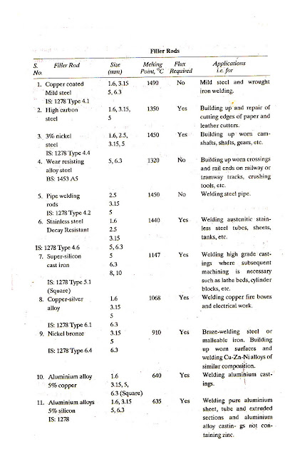
 Filler metal:

It is the material that is added to the weld pool to assist in filling the gap or groove. Filler metal forms an integral part of the weld. Filler metal is usually available in rod form. These rods are called filler rods. Filler rods have the same or nearly the same chemical composition as the base metal. Welding filler rods are available in a variety of composition and sizes. Some of them are given in the table below:

Flux:
During welding if the metal is heated or melted in air, oxygen from the air combines with metal to form oxides which result in poor quality, low strength weld or in some cases may even make welding impossible. In order to avoid this difficulty, a flux is employed during welding. A flux is a material used to prevent, dissolve or facilitate removal of oxides and other undesirable substances. A flux prevents the oxidation of molten metal. Flux may be used either by applying it directly on the surface of the base metal to be welded or by dipping the heated end of the filler rod in it. The flux sticks to the filler rod end. No flux is used in the gas welding of steel.
- Flux for welding cast iron: Fluxes for gray iron rods usually composed of borates or boric acid, soda ash and small amounts of sodium chloride,etc.
- Flux for welding stainless steel: Flux may contain compounds such as borax, boric acid, fluorspar, etc.
- Flux for welding aluminium and its alloys: The flux may be applied on the base metal by brushing and on the filler rod end by dipping the same into the flux paste just before welding. Fluxes employed for welding aluminium and its alloys are compounds of lithium, sodium and potassium and are obtainable in either paste or powder form.
- Flux for welding copper and its alloys: Flux is not necessary for gas welding of pure copper, however for copper alloys, borax based fluxes may be used.
- Flux for welding magnesium and its alloys: Flux must be applied to all edges to be welded and to the welding rod when welding magnesium and its alloys. A flux may contain sodium chloride, potassium fluoride, magnesium chloride, barium fluoride.
- Fluxes for welding nickel and its alloys: Gas welding of pure nickel requires no flux. However alloys of nickel such as inconel and monel require a flux to further clean the base metal and to break up the oxides that are formed as a result of the alloying agents. Flux for inconel may contain Ca(OH)2 , boric anhydride.
Wednesday, 15 August 2012 0
Introduction to Gas Welding:
Gas welding is a fusion welding process. It joins metals using the heat of combustion of oxygen/air and fuel gas that is acetylene, hydrogen or butane. The intense heat or flame thus produced melts and fuses together the edges of the parts to be welded with the addition of a filler metal.
Oxy-acetylene welding:
When acetylene is mixed with oxygen in correct proportions in the welding torch and ignited, the flame resulting at the tip of the torch is sufficiently hot to melt and join the parent metal. The oxy-acetylene flame reaches a temperature of about 3200 C and thus can melt all commercial metals which, during welding, actually flow together to form a complete bond. A filler metal rod is generally added to the molten metal pool to build up the seam slightly for greater strength. The maximum temperature of the oxy-acetylene flame is 3100 to 3200 C and the center of the heat concentration is just off the extreme tip of the white cone. Combustion of gas mixture is recognized as taking place in two main stages:

- Stage 1: Oxygen and acetylene in equal proportions by volume burn in the inner white cone. The oxygen combines with carbon of the acetylene and forms carbon monoxide and hydrogen is liberated.
- Stage 2: Upon passing into the outer envelope of the flame two more reactions take place as combustion is completed. The carbon monoxide uses the oxygen supplied from the air surrounding the flame and as a result of burning forms carbon dioxide. The hydrogen also burns with oxygen from atmosphere and forms water vapour. It can be seen that about 2/5 of oxygen necessary for the complete combustion of acetylene is got from the cylinder whereas the rest comes from the surrounding air atmosphere because of the need for supplemental oxygen from the atmosphere, the acetylene oxygen flame cannot be used inside of pipes or structures subjected to oxygen depletion from gas welding. By varying the relative amounts of acetylene and oxygen in the gas mixture in the torch, a welder can produce different flame atmospheres and temperatures as he requires.
Flame adjustment:
- To start with, when the oxy-acetylene gas welding torch is ignited, it gives an acetylene flame in which enough oxygen is drawn in from the atmosphere to burn acetylene partially. From acetylene flame, abundance of free carbon is released into the air. An acetylene flame may be used to apply carbon to mold faces in the foundry, because the carbon acts as an insulator between the molten metal and the mold face.
- As the oxygen valve in the torch is progressively opened, the flame becomes generally luminous. Then the luminous portion contracts towards the welding tip, forming a distinct bright zone within a blue outer envelope. This is a carborising flame and has large excess of acetylene.
- With further increase of oxygen content, the bright zone of the flame contracts farther and is seen to consist of two parts: a brighter inner cone and a pale green feather trailing off its end into the blue envelope, this is reducing flame.
- If at this stage oxygen flow is increased gradually, a certain point will reach where one will notice a distinct change in the sound of the flame and a well-defined white cone will appear near the tip, surrounded by a bluish envelope that is faintly luminous. This is neutral flame. There is an approximate one-to-one mixture of acetylene and oxygen to result a neutral flame.
- Further increase of oxygen content into the mixture will give rise to an oxidising flame.
To extinguish the flame and stop welding:
- When the welding or cutting operation is finished, close the torch acetylene valve first and then turn off the torch oxygen valve.
- Close the oxygen cylinder valve
- Release the pressure in the hose and regulator by opening the oxygen control valve on the torch.
- Release the pressure in the oxygen regulator diaphragm by turning the regulator to the minimum pressure position.
- Close the oxygen control valve on the torch.
- Repeat the same procedure for purging acetylene.
The chosen welding processes of practical significance in underwater welding are:
- Manual shielded meal arc welding, that is extensively used as a wet technique but is also suitable for habitate welding.
- TIG welding.
- MIG welding.
TIG and MIG welding processed have also been used to a limited extend for wet welding as well as more commonly in local enclosed gas shrouds.
1. Shielded metal arc welding:
Manual shielded metal arc welding is an economical process for underwater welding. This process can be carried out in all positions with the same success as welding in air. The DC welding equipment used for underwater welding must have a capacity of at least 300 Amps for each welder. All electrical leads, lighting gear, electrode holder, gloves, etc must be fully insulated and in good condition. Ferritic electrodes with a coated based on iron oxide should be used as they resits cracking, Positive polarity of work is preferred. This means that 65% to 75% of the heat is in the metal being welded. The weld pool is easier to handle and has enough fluidity to fill in undercut to a large extend. Electrode having positive polarity may have to be used for overhead butt-welding or welding cracks in the vertical and overhead positions. Current setting for underwater welding are normally higher than for welding air because there is a loss of heat by conduction through water and the control of these settings must be accurate to ensure consistent work.
2. TIG welding:
TIG welding has got the advantage that it gives a stable arc and less porous welds. TIG welding has been widely used, particularly for root runs. Although this process is relatively slow, it is very flexible and can accommodate variations in fit up and produce high quality penetration beads. TIG welding is preferred to MIG welding in dry welding as filler wire is manually controlled.
In TIG welding, as the depth (ie pressure) increases:
- The arc becomes constricted and the voltage increases for a given arc length.
- Tungsten tip starts getting eroded and this phenomenon influences weld bead width, and penetration. The erosion of the tip gives rise to arc instability when TIG welding is carried out at high pressure.
- Arc welding becomes more difficult.
TIG welding becomes restricted as the operating depth is increased.
3. MIG welding:
Because of the high cost of diving operations, it is highly desirable to complete welds in the shortest possible time. This has directed attention to the use of semi-automatic processes using solid wires or flux code wires. Wires containing oxidising and reducing elements give good results even without shielding. MIG welding is faster and less expensive that TIG welding. Arc heat increases with the depth of water so filler metal melts fast CO2 or Argon is used as shielding gas. The shielding gas gets denser and may require flow rates upto 10 times the surface rates. MIG dry welding is preferred to MIG wet welding for better results.
International interests to develop and utilize oceans which cover 70% of the earth and its resources such as development of offshore gas and oil field, fisheries multiplication, large offshore construction and mineral resources, mining in the sea bottom,etc; have let to the development of underwater welding. Underwater welding has been used for temporary repair work caused by ships collisions, unexpected accidents, corrosion and other maintenance works.
Types of Underwater Welding:
Following are the types of underwater welding:
1. Wet welding
2. Dry welding :
1. Hyperbaric welding
2. Cavity welding
Saturday, 11 August 2012
 |
| Cam and follower (Image credit:cnx.org) |
A camshaft is simply a shaft on which cams are mounted. The camshaft is mounted in bearings in the lower part of the cylinder block in most inline engine. In few engines, it is located on the cylinder head. A cam is a device that changes rotary motion of the camshaft into linear motion of the follower or lifter. The cam has high spot or love the follower riding on the cams will move away from or toward the camshaft as the cam rotates. A camshaft is responsible for opening the valves. A camshaft has a number of cams along the length, two cams for each cylinder, one to operate the inlet valve and the other the exhaust valve. The camshaft is driven by the crankshaft either by a pair of meshing gears or by means of a pair of timing sprockets connected by a chain. The camshaft turns at half the speed of the crankshaft. The gear and sprocket maintain a definite time relationship between the camshaft and the crankshaft to ensure opening the valves exactly at the correct time in relation to piston position.
Saturday, 11 August 2012 0
 |
| Valve (Image credit: rexresearch.com) |
Valve is a device to close and open a passage in motor vehicle engines. Two valves are used for each cylinder - An inlet or intake valve and an exhaust valve. Fuel is admitted to the cylinder by the inlet valve, and the burnt gases escape from the exhaust valve. When closed, the valve must seal the combustion space tightly. The valves are usually made of Austenitic stainless steel which is a corrosion and heat resisting material. Exhaust valve is usually made of silchrome steel which is an alloy of silicon and chromium with unusual resistance to heat. Inlet valve being subjected to less heat is usually made of nickel chromium alloy steel. The valves used in modern passenger car engines are termed as poppet or mushroom valves.
Valve mechanism:
Valves are operated by cams mounted on a camshaft. The camshaft gets motion from crankshaft. As the camshaft turns the cam operates the valves. According to the location of the valves, the valve mechanism are of two types:
- Valve mechanism for operating the valve in engine block ( Straight poppet valve)
- Valve mechanism for operating the valve in cylinder head ( Overhead poppet valve)
Flywheel is a heavy steel wheel attached to the rear end of the crankshaft. The size of the flywheel depends upon the number of cylinders and the general construction of the engine.
 |
| Flywheel (Image credit: casting quality.com) |
The flow of power from the engine cylinder is not smooth although the power impulses in a multi-cylinder engine overlap or follow each other to provide a fairly even flow of power, however additional leveling off of power impulse is required. This is done by a flywheel. To understand the function of a flywheel in a better way, take the example of a four stroke, single cylinder engine. There are times when more power is being delivered than at other times. This tends to make the crankshaft speed up and then slow down. The engine delivers power during one stroke only - the power stroke and it absorbs power during the other three strokes - to push out the exhaust gases, to intake fresh charge in the cylinder and to compress this charge. Thus during power stroke, the engine tends to speed up and during the other three strokes, it tends to slow down. The inertia of the flywheel tends to keep it running at constant speed. When the engine tends to speed up, the flywheel resits it. When the engine tends to slow down, the flywheel resists it. Thus the flywheel absorbs energy as the engine tries to speed up and gives back energy when the engine tries to slow down, keeping the engine speed almost constant.
Flywheel is also used as a part of clutch mechanism and fluid drive unit. The flywheel also has a teeth on its outer edge to mesh with the electric cranking motor driven pinion when the engine is being cranked to start it.
Crankshaft is the first part in the power transmission system onto which the reciprocating motion of the piston is converted into rotating motion with the help of connecting rod. A crankshaft consists of crank pin, crank arm, balancing weight and main journals. Big end of the connecting rod is connected to the crank pin of the crankshaft. Center to center distance between the crank pin and crankshaft is half of the piston displacement during a stroke. Thus one complete revolution of the crankshaft makes two stroke of the piston. The parts of the crankshaft inside the main bearings are called the main journals. The crankshaft is supported by the main bearings on the main journals. Balancing weights are provided on the opposite side of the crank arms for balancing.
 |
| Crankshaft (Image credit: gasgoo.com) |
 |
| Connecting rod (Image credit: race.nangreaves.com) |
The connecting rod is the connection between the piston and the crankshaft. It joins the piston pin with the crank pin. Small end of the connecting rod is connected to the piston pin and larger end to the crank pin. The function of the connecting rod is to convert linear motion of the piston into rotatory motion of the crankshaft. The connecting rod usually has I-beam cross-section and made of forged steel. Aluminium alloy is also used for connecting rods. They are carefully matched in sets of uniform weight in order to maintain engine balance. The connecting rod carries the power thrust from piston to the crank pin and hence it must be very strong, rigid and also as light as possible.
Subscribe to:
Comments (Atom)


